A thorough examination of the history and current methods for varnish prediction, prevention and mitigation techniques from a service provider’s perspective.
Introduction: Prediction, Prevention & Mitigation
As a service provider with thirty years of experience in industrial lubricants, it became apparent during the mid-1990’s – early 2000’s North America power generation boom varnish is a problem. Peak Power Plants were being constructed and the constant heating and cooling were wreaking havoc with their servo valves. Lubricant manufacturers and turbine manufacturers were in a disagreement on whether it was the turbine designs or lubricant properties.
In most cases, it is a little of both. Hydraulics with tight clearances pull oil from the same reservoir as the bearing lubrication. These valves were exposed to higher temperatures of bearing lubrication and the standard lubrication formulations of the time did not have the same life as previous applications.
As any reputable service provider will tell you “service provider = solutions provider”. We were receiving multiple request for help on the subject. This paper will cover the advanced solutions we have developed while helping plants deal with these varnish mitigation issues.
There are many white papers in the field around prediction and prevention of varnish, however it was difficult to find any documentation that covered mitigation from a service provider’s perspective when conventional prevention is just not enough. This paper will have a stronger focus on the mitigation side, however it would be incomplete if it did not include some of the advancements in prediction and prevention strategies.
Prediction
TOTAL ACID NUMBER (NOW ACID NUMBER)
During the early 1990’s the first indication of varnish was either through visual staining of components reported from maintenance personnel in the field or an increase in the TAN (Total Acid Number ) number during routine analysis. One of the side effects of increased acid in turbine lubricants is a depletion of antioxidants and oxidation of the oil, creating varnish. The limitation of this test at the time was that by the time the TAN number was increasing, varnish had already accumulated to the point an economical varnish filtration plan wouldn’t work.
ULTRA-CENTRIFUGE
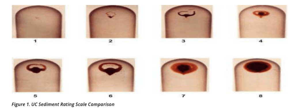
As service providers we reached out to oil manufacturers to see if there was a better way to predict varnish. Mobil Oil had been using a process called UC or Ultra-Centrifuge Process. This process took a sample of the fluid and spun the oil at 17- 20,000rpm’s for 30-mintues, creating gravitational forces reaching 34,800g’s. The force effectively extracts the sludge and varnish precursors, driving them to the bottom of the tube.
The concentrated material is then compared to a visual sediment-rating scale. (Figure 1). Using the 8-step system:
- The first signs of varnish deposit potential coincide with a rating of 4-5
- Values of 5-6 indicated a borderline condition and the need to increase monitoring
- A rating of 7-8 indicated that the oil had reached its saturation point for carrying varnish and deposits were plating on steel components in the system.
The UC test was vital for a service provider in developing a mitigation plan where if the rating was at a 6 or higher the lubricant was already at a saturation point and was not able to use the current mitigation process. We will take a closer look into why during the mitigation section of this paper
MEMBRANE PATCH COLORIMETRY
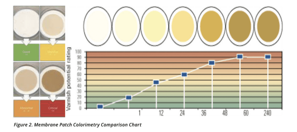
The Membrane Patch Colorimetry test – or MPC – is used to measure the color bodies of insoluble contaminates found in the lubricants. The test uses solvent extraction to capture varnish and oxide insoluble contents from a sample pulled through a .45-micron filter- membrane (or patch).
Varnish material is not very soluble in the oil/solvent mixture and tends to color the patch. By measuring the hue (See Figure 2) a general characterization is made about the level of varnish in the system. By monitoring the level of insoluble material informed decisions can be made around varnish mitigation. MPC-testing can be biased against some antioxidant chemistries that produce dark deposits, so care must be taken when assigning specific ratings.
RULER
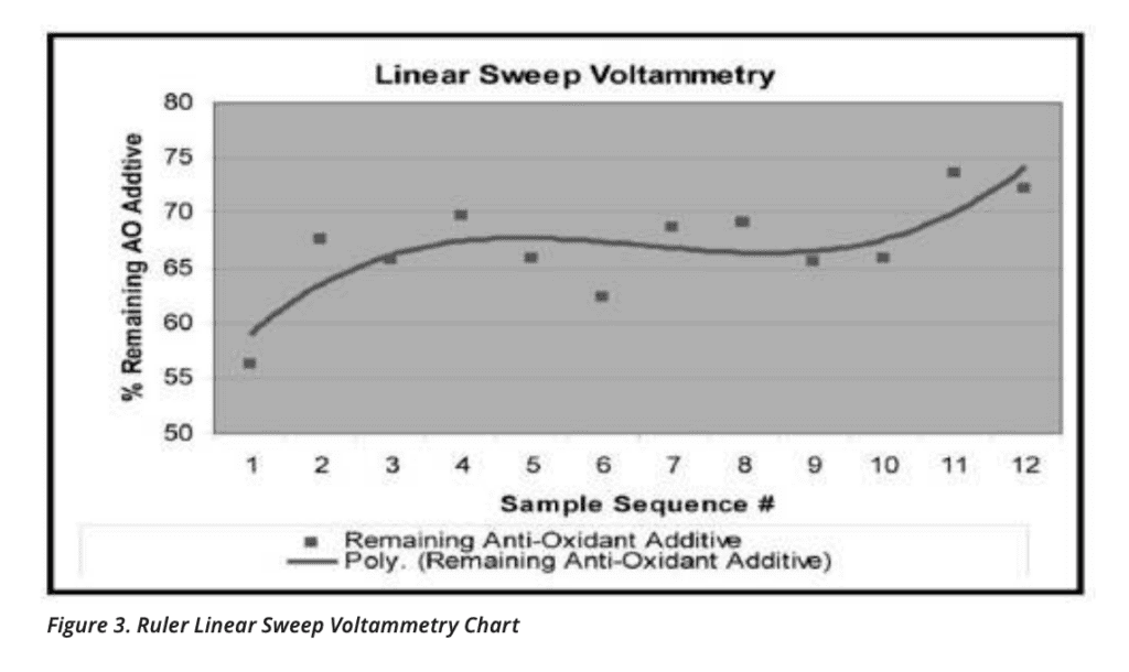
The Remaining Useful Life (Ruler) test is used to measure active antioxidants left in lubricant. The test measures antioxidant depletion in current fluid vs. virgin products utilizing voltage differential (Figure 3). Antioxidants are the most important additive component in many lubricants. With this information, you can get a picture of the health and life left in the lubricant.
Many turbine oil antioxidant packages have a mixture of amine and phenolic antioxidants. These packages vary by type and blend ratio. Therefore, it is very important that the testing lab has an appropriate reference sample from which to measure the change the antioxidant levels. The caution limit for Ruler is at 25 percent of the remaining antioxidant, which is typically the amine.
Laboratories have listened to clients and have started offering new tests or including them in standard testing packages. Historically, standard test packages included Karl Fisher (Water %), ISO Code (Particle Count), TAN (Now just AN – Acid Number), and IR Spectroscopy (Specific additive and contaminants).
Most modern laboratories have developed two new offerings. An Annual Turbine Analysis (ATA) and a Varnish Potential Analysis (VPA) can be set up to incorporate all of the tests utilized today in measuring varnish. While interviewing laboratory representatives it became clear that there is no linear correlation across the varnish predictions tests. In other words, a UC of 6 does not always correlate to an MPC of 30 and the Ruler at 45. These can be different due to life of product, specific exposure to heat, what temperature, additive package and the base product of the lubricants.
Each test measures a different aspect to current state of the lubricant, which is why the labs offer the all-inclusive testing. Clients want as much data as possible to catch potential varnish issues prior to going into an unscheduled outage.
Prevention
There is some debate on how prevention and mitigation are defined. Many of the items listed in the prevention section are actually mitigation techniques. In explanation, I have decided to divide these economically. Using “prevention” as methods negating the need for a full change of lubricants and downtime.
Lubricants and oils that have experienced severe oxidation and heavy varnishing may not be adequately reclaimed or filtered to continue useful service. However, in most cases, varnish and other soft contaminants can be removed from the oil and the oil returned to service. Listed below are units that are utilized for varnish removal. For the interest of the article the units are listed in the timeline of the order we saw the technology hit the mainstream marketplace.
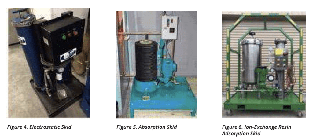
ELECTROSTATIC SEPERATION
Electrostatic separators operate in a low-flow, off-line or kidney-loop installation. They operate on the premise that charged particles precipitate to a collection media or plates of the opposite charge. Disadvantages reported when using electrostatic separators include high purchase cost and operational costs, low varnish holding capacity of collection media, efficiency drops with the presence of water in the oil (500 ppm or greater), low flow rates and complex control systems.
ABSORPTION SYSTEMS
Absorption systems are also installed in an off-line or kidney-loop manner. Unlike electrostatic units, absorption units can provide a higher range of flow rates, from low flow (<5 gpm) to high flow (>50 gpm). The absorption media commonly used in off-line filters is a high-density, depth- type cellulose filter. With these filters, it is possible to combine particle, moisture and varnish removal in one system.
ION-EXCHANGE ADSORPTION SYSTEMS
This adsorption method uses a form of Ion-exchange for varnish mitigation or removal. Selective ion-exchange resins are mixed and formulated to adsorb varnish within its porous structure. This adsorptive nature is due to polar attraction between ion exchange resign and varnish contamination. There are large amounts of surface area by volume, making this process highly effective. Like the adsorption units the ion-absorption methods are capable of higher flow rates. Units range in size from 5gpm – 20gpm and can be scaled larger by installing additional elements.
In order for any of the units listed above to be effective it starts with having a solid predictive program. Over the years it has not been uncommon to be walking through a power plant and see one of the units above sitting in a corner collecting dust. When questioning the maintenance manager(s) the most common response is “it didn’t work”. Which always leads to the follow up questions of why.
Trying to understand using root cause (or the ‘Five-Why’s) will get to some interesting information. Fairly commonly, customers incorrectly think varnish removal equipment can be applied to all systems regardless of size. Knowing your level of contamination, the size of the reservoir, and historical data is key to sizing the right skid for the job.
The second most common problem is that the system worked for a while, the varnish was decreasing, then it just stopped and eventually started creeping back up. Digging deeper, the majority of the sites never changed the filter media.
Maintenance personnel are used to looking at a differential pressure gauge to determine when a filter is plugging. While that works with most filtration units it is possible for the resin-based units to level out with varnish removal and not reach the required differential to trigger a change. This is where analysis comes back into play. If a unit is dropping the MPC from a 40 to a 30 and levels off it can indicate the need for a change.
It is important when renting or purchasing a piece of equipment that part of the program is education on the proper operation and monitoring of the unit. As a service company it is important to client organizations that we do not just send the equipment out; we must develop a full program with operating and testing instructions.
SWEETENING
Sweetening the oil refers to performing a partial change of current lubricants. The percentage can vary but most common is between 10-50% of system volume. The effectiveness of sweetening the oil is based on the level of contamination. If performed early enough (When MPC is <25) performing a blend with new oil can extend the life of the existing product.
However, if the level of contamination is already at an MPC rating >40 performing the sweetening process is no more than installing a band aid. This service does not pull varnish out of the remaining oil or from components where varnish has dropped out. This is more of a dilution of contaminants and replenishment of the additives (including the anti-oxidants).
ANTI-OXIDENT REPLENISHMENT
Technology has come into play where under controlled circumstances the anti-oxidant package can be replenished. This translates to longer lasting oil with lower levels of sludge and varnish. The process is customized specifically for each system to rebalance the additive to optimal level. While the technology is sound not every in-service oil is suitable for additive replenishment. That along with oil manufacturers resistance to a third party messing with their formulations, this process is a hard sell.
Mitigation
In the early years, many of the preventative technologies had not come into play. The power generation industry sector was having trouble with “Peaker” plants – peak power plants only triggered when demand was high or other plants went out of service. These plants are contracted to supply power within a certain timeframe of receiving a call and come down to turning gear while on standby.
Once the systems are put into turning gear, the hydraulics would cool and varnish deposits would plate out to the steel in the hydraulic valves, including the small “last chance” and pencil filters found in these valves. Issues would arise when trying to get power to the grid within the timeframe allotted. Varnished valves do not move, requiring plant maintenance to scramble to the units and manually activate or clean the filters.
At one plant in Vegas the Maintenance team kept spare valves on hand to perform a quick change out if needed. Rebuilding valves, replacing valves and paying fines creates a financial burden on facilities.
In years since, we have found many new plants that were both peak and base-load have similar issues. Many of these plants are using the final fill oil to perform commissioning flushes. During the commissioning flush, lubricants were picking up all the rust preventative and any other materials used during installation. STP, break cleaner, solvents, and rust preventatives were escalating the degradation of the anti-oxidants and other additives in the lubricants, building varnish earlier than expected.
Although there have been many improvements made to the process developed over 20 years ago the principal remains the same. The full mitigation process has been widely recognized by both major oil manufacturers and customers as the preferred method of varnish removal when exceeding a level that filtration techniques can help. One petrochemical company has gone as far as incorporating the following method as preventative maintenance every six years during their major turnarounds.
We have also seen many power generation sites incorporating the mitigation process during any oil changes. With the greatest cost (replacement fluids) already being incurred, this has become a feasible preventative maintenance practice.
The mitigation process uses an oil-soluble, solvent-free cleaner that contains emulsifiers, dispersants, and rust inhibitors. Think of it is a detergent used to get that hard ground in dirt off of your clothes. We use this product due to the fact that it is mineral based and compatible with common seals up to a 20% concentration. The cleaner has a high flash point to allow systems to operate normally during the cleaning process.
Varnish Mitigation
As with the predictive and preventative sections, it all starts with the analysis. Early on we used the UC rating to determine whether the oil was suitable or not. Today we can use either UC or MPC rating. It is vital to verify that the existing oil can even carry varnish during the mitigation process.
If the lubricant is at its saturation point and cannot solubilize and carry the varnish the process is ineffective. If the current lubricant has a high MPC (>35) or UC (>4) it will require running a varnish removal skid prior to the project, sweetening the oil, or a full charge of base stock to be used during the mitigation process.
Phase one of the process uses 5-10% added to the current (or base stock) lubricant and running with system pumps in normal flow path for 72-hours. The fluid needs to be kept above 120F. Hydraulic valves are forced into an open position allowing continuous flow. If this is not possible the valves should be stroked open and closed at a minimum of hourly. Side stream filtration with a 2.5Micron Beta1000 filter is recommended during the 72-hour circulation.
At the end of 72-hours the system is drained while hot including reservoir, low point drains, filter vessels, coolers and even feed headers. The reservoir is entered and a cursory cleaning of any heavy drop out and residual oil is removed.
Phase two consists of filter replacement and charging system up with a base oil to the low point of operating level. The oil is circulated using system pumps and repeating hydraulic valve manipulation for a 12-hour period. At the end of the 12-hour circulation purge phase the system is drained again utilizing the actions listed in phase one. The reservoir is cleaned to meet client’s cleanliness specifications.
Phase three requires a final filter change in both the system and side stream filtration. The final fill oil is filter filled into the reservoir to meet OEM ISO Code requirements. Once full, the system pumps are started while side stream filtration takes place to verify ISO Cleanliness throughout the system.
Once the system is clean and has “new” lubrication the susceptibility of varnish still exists. It is recommended to put the system on a sampling program as outlined in the Predictive section. If the system is critical or highly susceptible to varnish a full-time varnish absorption system is recommended.